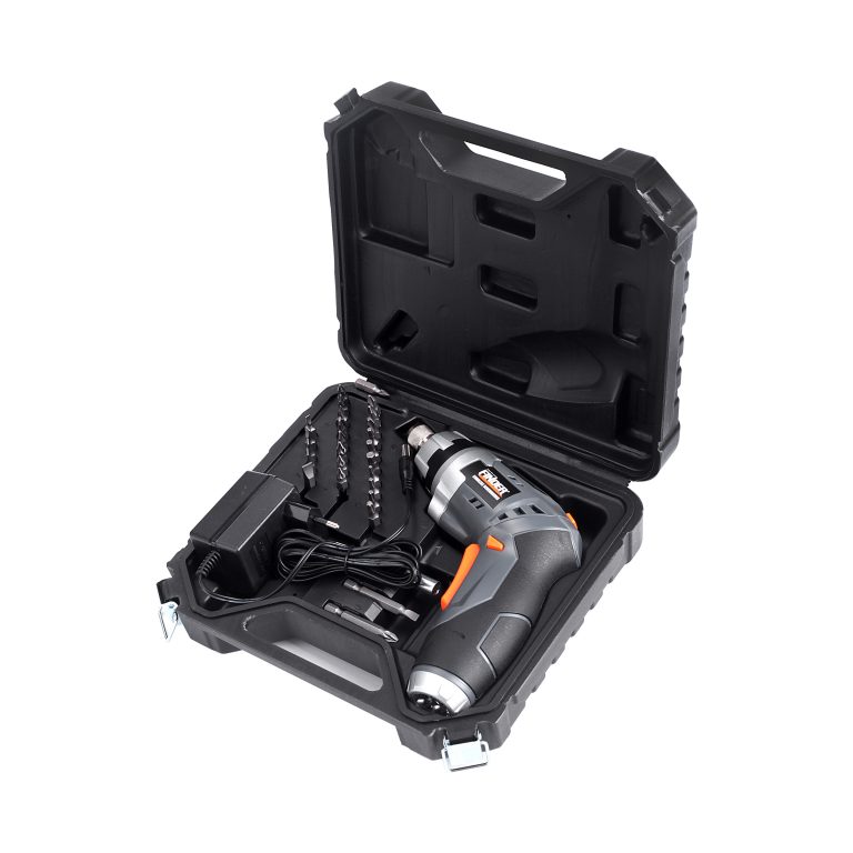
If the electric screwdriver is broken, how should it be repaired? Now let me share with you some points to pay attention to during maintenance.
1. Maintenance tools
Two multimeter pieces (one for simulation and one for digital, analog type is indispensable), diagonal pliers, pointed pliers, soldering iron, and soldering iron holder. Solder flux, tin wire, solder absorber, fine sandpaper, heat shrink tubing, wire stripping pliers, flat screwdriver (one small and one small), cross screwdriver (one small and one small, plus one rubber handle screwdriver), graphic knife.

2.Circuit working principle
1. Process
Input (protector, microswitch) → Rectification → Filtering → Forward and reverse switches → Motor → Clutch
2. Normal parameters of each electronic component
(1) Power cord: Measure the DC resistance value, and the normal value approaches zero; Common faults: open circuit or poor contact (broken).
(2) Micro switch: measure the resistance value between normally open (resistance approaching infinity) and normally closed (resistance approaching zero); Common faults: Poor contact of contacts (burnt black), inability to reset buttons properly, and body rupture.
(3) Protector: measure the resistance value; Normal is zero; After mild overload, it can automatically reset, but if it is too large, it will permanently fail. It can also be disconnected in the event of high temperature (thermal protector), and can automatically reset at room temperature.
(4) Rectifier bridge: Short circuit the output terminals (+, -) and measure the DC resistance (around 15K) of the output terminals (+, -).
(5) Front and reverse switches: The pin corresponding to the toggle key is a common pin, and the two gears corresponding to the toggle key are connected.
3.Circuit detection analysis
After receiving an electric batch with an unknown cause of malfunction, preliminary testing should be carried out first, as follows:
Set the multimeter to the (× 1K) position to zero, turn on (press) the microswitch, and measure the DC resistance at the input end. The positive value is around 15K (the digital multimeter is set to the diode and shows a voltage drop of around 1.0). This value indicates that the electric screwdriver circuit is working properly. Another way to test the circuit is to open the electric screwdriver and short circuit the two poles of the motor. Under normal circumstances, The measured DC resistance value at the input end is slightly lower than the initial maximum value (the motor DC resistance value is not included in the calculation).
4.The components of the motor
1. Basic components: armature (rotor), carbon brush holder, motor front cover, bearings, magnet (stator), carbon brush, motor gasket.
(1) Armature: The most important component of the electric screwdriver, like the heart, the state of the armature will determine whether the screwdriver can work properly. The quality of the armature: We can determine it by measuring its DC resistance. Under normal circumstances, the DC resistance (220V) between adjacent poles of an armature commutator is about 15 ohms higher (due to differences in manufacturers, their values also vary, with larger DC resistance exceeding 20 ohms).
Damage characteristics and fault analysis: A. Judging from the appearance whether there is obvious wear on the commutator of the armature. Armatures with severe wear have high noise during operation; B. Judging whether the central axis of the armature has become smaller (after installing the bearing, the bearing can sway left and right). When it is more obvious, the center of rotation of the armature is unstable and the noise is also high. C. Many armatures cannot function properly due to an open circuit between adjacent poles of the commutator. When there are multiple disconnections, the motor cannot start; When there is a disconnection, the motor can work, but if it happens that the carbon brush is in contact with the disconnection, the motor will stop working.
(2) Carbon brush holder: Judging from its appearance whether it is damaged or internally carbonized (burnt black).
(3) Motor front cover: Judging from its appearance, it is damaged.
(4) Stator: Judging from its appearance whether there are any damages or displacement elements on its internal disk (causing magnetic asymmetry), and at the same time, a flat screwdriver can be placed inside the magnet to check its magnetic strength. If the magnetic strength is too low, a new magnet should be replaced.
(5) Bearing: Judging from the rotation of the bearing, there is a jamming phenomenon. When the internal friction is strong, the motor noise is relatively high.
(6) Carbon brush: When the carbon brush is worn to the remaining two or three millimeters, replace it with a new one (replace it regularly).
(7) Gaskets: Fix the armature to prevent shaking up and down, ensuring stability. Appropriate number of gaskets; The armature will not shake up and down, and can be twisted with less force.
5. Clutch
1. Common clutch faults:
(1) Unable to lock the screwdriver head: A transmission shaft is damaged, replace the transmission shaft (the steel ball groove becomes larger, and the steel ball automatically falls off);
(2) Missing steel balls, replace with new ones.
2. Damaged transmission shaft:
(1) Visually, there is severe wear on the head of the screwdriver, which needs to be replaced;
(2) Internal fracture: The testing method is to install the fan blade into the clutch, then lock it, use a flat screwdriver to twist the transmission shaft, judge the sense of detachment, and determine its quality.
